Image B&C
This content provides detailed information about control of image brightness and contrast. It is intended for users of the Scan Control and the DISS6 apps.
Brightness & contrast described here does not refer to the physical display, but to how the software renders the image on screen!
Background information
Control of image display for brightness and contrast is necessary because human vision is limited in the number of grayscale levels it can perceive. Whereas image data may contain 256 (8-bit) or 65,536 (16-bit) gray levels, human vision is limited to a much smaller number of gray levels, on the order of 10 gray levels, depending on environmental light and hardware display specifications.
Whereas it's possible to change pixel values so that minimum pixel becomes 0 and maximum 65,535, such processing is computationally expensive and looses the original pixel values in the image, and it's therefore undesirable and avoided where possible. For the case of grayscale images, either 8-bit or 16-bit, it's more efficient to change the way pixel values are mapped into gray values, i.e. the image palette.
What is image palette?
Palette list a look up table of grayscales, or color values, that gives control over how the image is displayed on screen without any changes to image data. It is often used to map gray levels into different colors, as human vision excels in perception of colors, however this page will focus on palette changes for gray scale display only. Image palette is also required by the operating system (e.g. Microsoft Windows) that uses Index8 bitmap images in its display graphics - that is 8-bit images with a 256-levels palettes. In practice, any 8-bit or 16-bit image data is converted into an Index8 images for display, and image palette is part of the usual tools to manage this conversion.
Usual microscopy data results in 8-bit, 16-bit or higher bit depth image data that is mapped into Index8 images, typically with grayscale palette that run from back to white. If relation of contrast to physical quantity is inverted, or image perception requires a positive/negative process, then the palette is inverted so that it runs from white to black.
A color image, that is an image where each pixel has a color value and optionally a transparency value, does not require and does not have an image palette.
What is image range?
Image range is a pair a values and units that give the minimum pixel value and the maximum pixel value displayed on screen, with the corresponding physical units. Physical units may be Analog to Digital Conversion (ADC), volts (V), amperes (A) or other such experimental or calculated values.
Image range is distinct from the minimum and maximum pixel values in the image data. If image range is well balanced to a grayscale palette, then image range is set to minimum and maximum pixel values in the image data.
Range is a convenient approach to compare images, either in a time-lapse as part of an in-situ experiment, or to compare images of the same sample between microscopes as part of a round-robing experiment, or to compare images across different samples. Because range can have physical units, all images in the comparison can be set to the same range and palette, for a visual comparison or an animation.
What are image brightness and contrast?
Brightness describes an increase or decrease in range (add/subtract operation) that makes the entire image lighter or darker. Contrast control describes an increase or reduction in range (multiply/divide operation) that makes the light features in the image lighter and that dark features in the image darker.
Brightness and contrast controls for image display reproduce the same concepts as for detector control and therefore may be more natural for users familiar with acquisition hardware, however they don't lend naturally to image processing in microscopy as they have a relative and more complex relationship with image display compared with image range.
- For the case of grayscale images, B&C are therefore operations to the image range. Since image range works together with image palette, B&C changes results in changes of image display on screen.
- For the case of color images,
How does image B&C automation work?
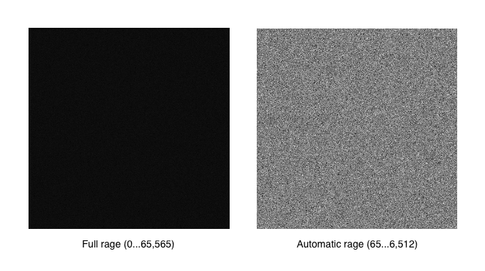
Consider a 16-bit image where the minimum pixel value is 65 and maximum pixel value is 6,512. If the image is displayed at its full range where pixel value 0 is set to black and pixel values 65,535 is set to white, then the image will appear flat even if data is present. However if the same image is displayed such that the minimum pixel value of 65 is set to black and the maximum pixel value of 6,512 is set to white, then the image content becomes visible - as illustrated below.
Scan Control app
Before considering image B&C, set detector B&C controls for image acquisition to ensure that raw image data is not clipped!
Controls for adjusting image brightness and contrast on screen are given with the Range selection menu in the Palette section of the View toolbar, where range can be selected to full or automatic.

For the first frame in the acquisition, Scan control will monitor each new image data chunk as it arrives from the scan controller and determine minimum and maximum pixel values in the current frame pixel values, and adjust the image palette accordingly. Depending on signal levels in the frame, this may result in a continuous adjustment of black and white levels as the image is scanned. For the following frames, Scan control will use the minimum and maximum pixel values from the previous frame to avoid repeating this dynamic scaling of black and white levels with each new frame.
Scan control app does not provide controls for manual control of image B&C or range, for that please use offline processing with microDIP. Image range saved in image metadata, for each frame in the image, and are reused in the microDIP software.
Scan Control does not have access to detector brightness & contrast, as these belong to the detector, not the scan controller - see the previous page on this B&C how-to about detector controls.
DISS6 app
Before considering image B&C, set detector B&C controls for image acquisition to ensure that raw image data is not clipped!
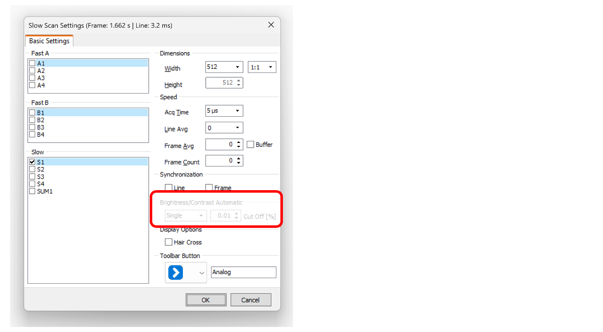
DISS6 software provides controls for automated image brightness and contrast in the scan settings dialogue, that can be open by right clicking on a scan profile button, see the "brightness & contrast automatic" section. It can be set Single, Global or None with a Cut Off default value of 0.01%.
- Single determines individual image range for each signal in the scan, which results in individual image B&C for each signal in the scan
- All determines image range for all signal in the scan, which results in the same image B&C applied to all signals in the scan
- None uses full image range
Further behavior of the automated B&C is set in a configuration file read at app start and not available to the end user in the DISS6 user interface. On a scan start, every new image data chunk is analyzed as it arrives from the scan controller to balance the image range for display to minimum and maximum pixel values in the current frame. Then for every subsequent frames, image range is
- continuously adjusted throughout the scan as new pixel values arrive. For fast scans with large changes in intensity across the image, this may result in an undesirable image flicker of screen.
-
adjusted only once at frame start to pixel values from previous frame. This prevents the image flicker above.
DISS6 software does not provide controls for manual control of image B&C or range, for that please use offline processing with microDIP. Image range saved in image metadata, for each frame in the image, and are reused in the microDIP software.
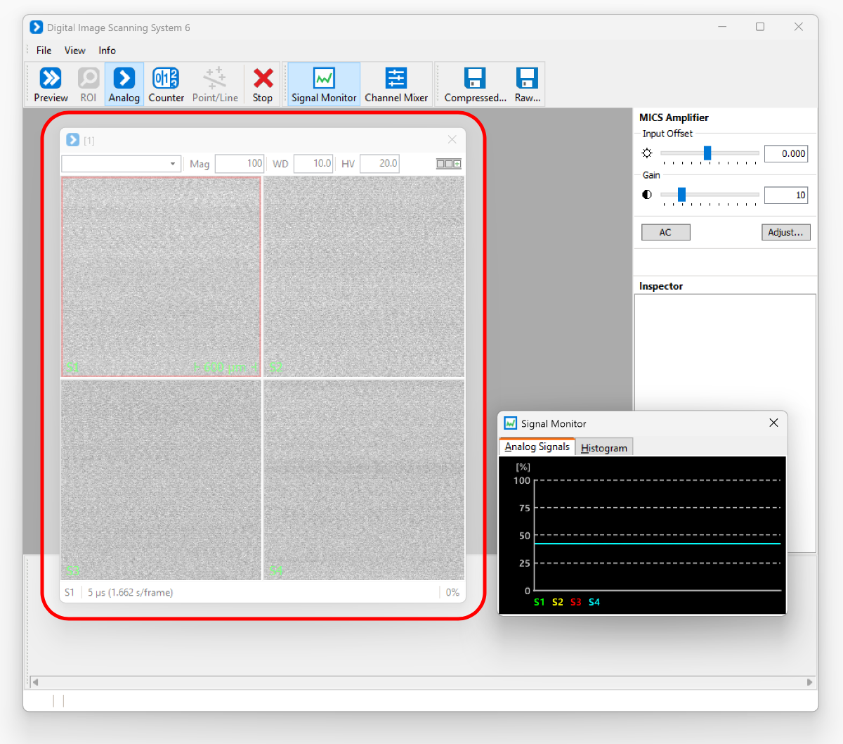
Single auto
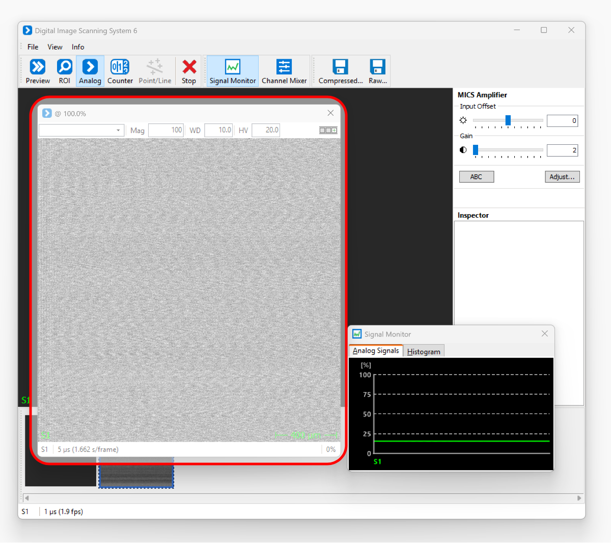
Each signal will be monitored independently to identify the minimum and maximum pixel values, with the specified cutoff (%), then the black and white levels will be defined accordingly. Each image will then have a different blank and white level. Note in the screenshot below how the display brightness & contrast are adjusted automatically to achieve strong contrast even for a very faint background noise - true scale is shown in the signal monitor as an apparent perfect green line.
All auto
All simultaneous signals will be monitored independently to identify the minimum and maximum pixel values, with the specified cutoff (%), then the same black and white levels will be defined for all images.
microDIP app
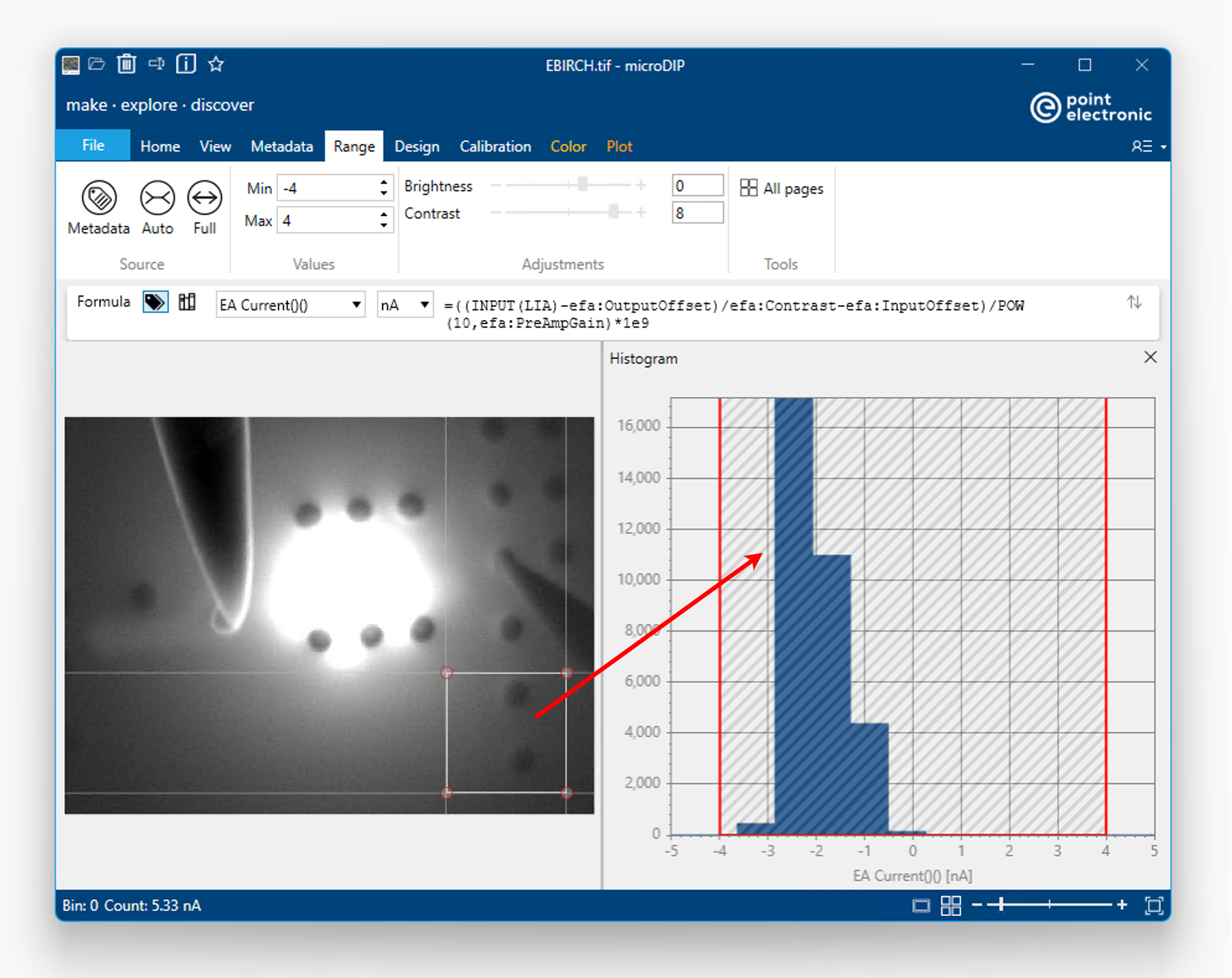
MicroDIP app offers advanced control of image B&C in
- the Range toolbar in the Ribbon
- the Histogram tool
see screenshot below.
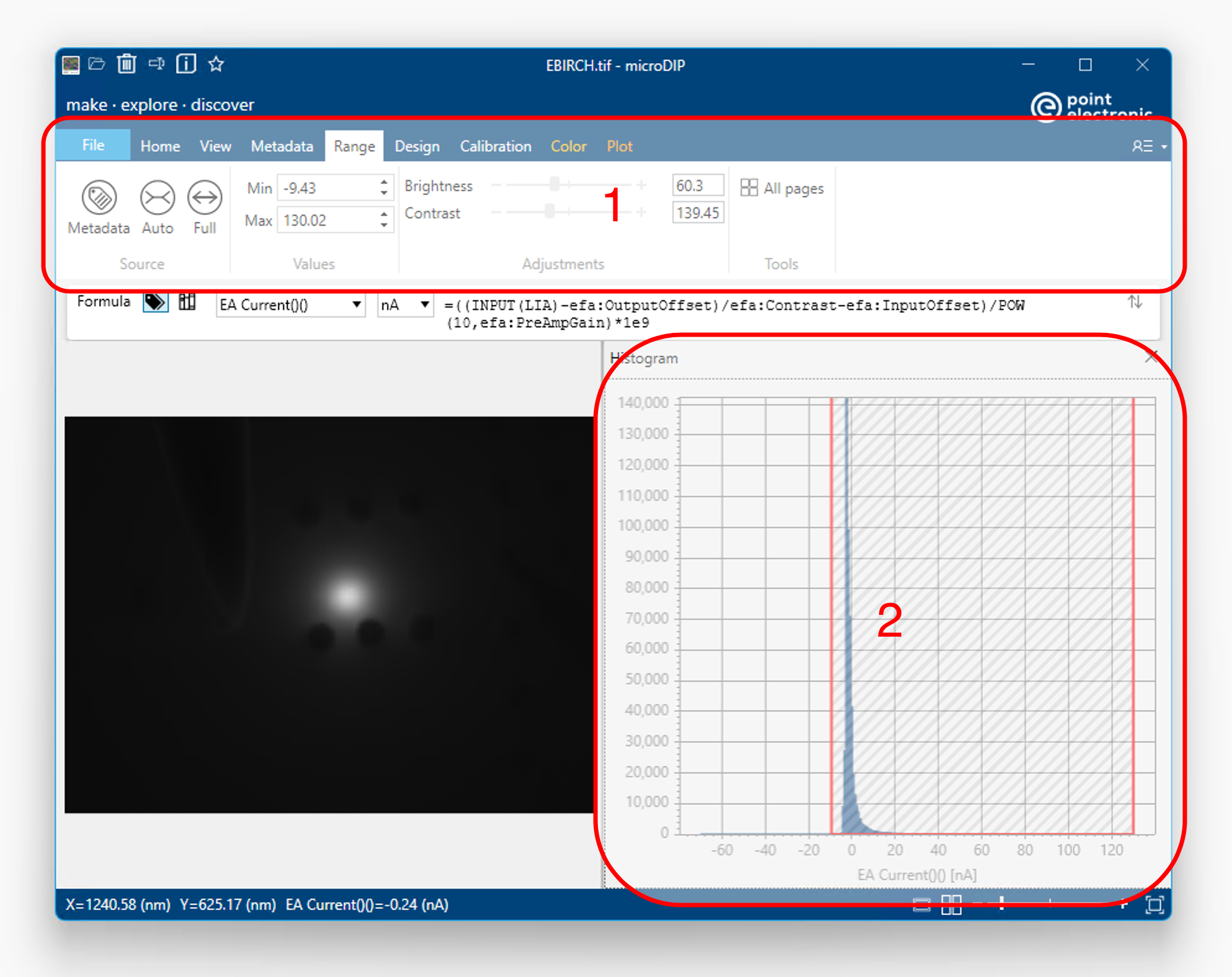
Image range image range may be take from the metadata, calculated from the image pixel value to match minimum and maximum values, or fit to the full bit depth of the file - see the Source group in the Range toolbar. Note that span in the Histogram tool will also update to display the image range used. Values in the Range toolbar can be applied to the single selected signal, or they can be applied to all signals in the file with the "App pages" button.
Image range can be input manually in the Range toolbar, in the units as selected in the Formula toolbar, or modified in the image histogram tool by clicking and moving the two limits of the spans in the Histogram tool.
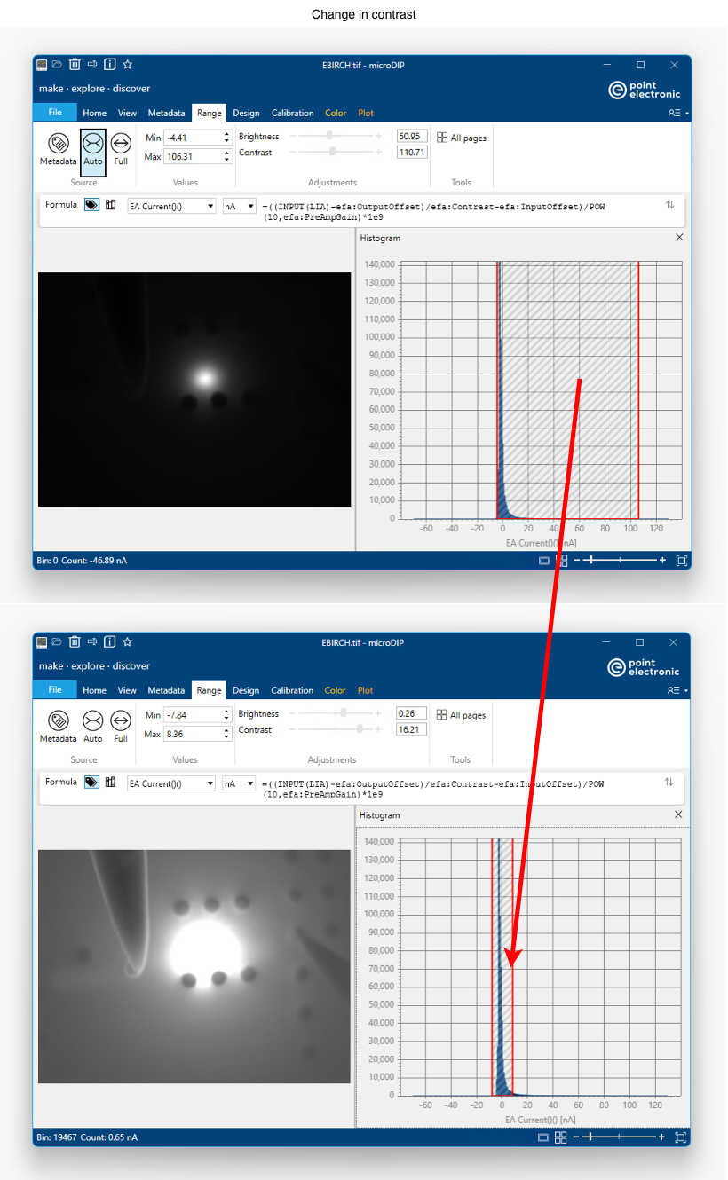
If B&C controls are preferred, their sliders and text input fields are available in the Range toolbar, again in the same units as the Formula toolbar. Contrast value is the difference between min and max values in the image range - changes in contrast result in widening or narrowing of the span in the Histogram tool.
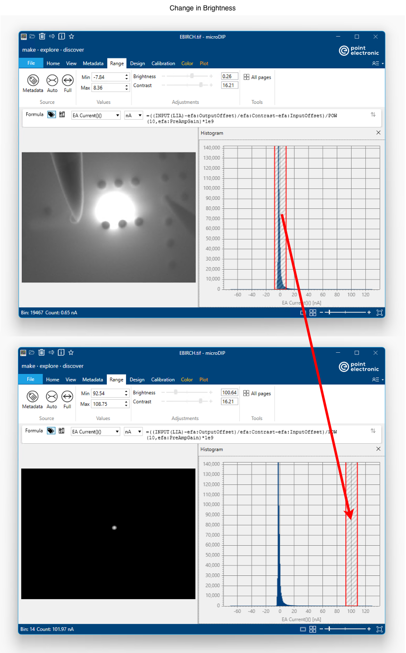
Brightness value is the average of min and max values in image range. Changes of brightness result in corresponding moves of the span in the Histogram tool
Histogram tool can be used in combination with an area selection, either round, square or rectangular, to adjust image B&C to particular subregions in the image.