Detector B&C
This content provides detailed information about control of detector brightness and contrast. It is intended for users of the Detector Control and the DISS6 apps.
Background information
For perfectly balanced acquisition, hardware brightness and contrast (B&C) must be set such that minimum and maximum levels in the output of the detector match to the minimum and maximum input levels in the scan controller - i.e. output and input ranges are matched. If acquisition is not well balanced, then the signal acquisition may be clipped and data may be lost.
What are detector brightness and contrast?
Brightness control describes an increase or decrease in range (add/subtract operation) that makes the entire image lighter or darker. Brightness is sometimes described as an offset, particularly when described in relation to the main amplifier of the detector. In more complete amplification terms, an amplifier usually has an input offset and an output offset, where
- input offset is the usual Brightness controlled by the user
- output offset is service access only.
Contrast control describes an amplification or reduction in range (multiply/divide operation) that makes the light features in the image lighter and that dark features in the image darker. In reference to the detector amplifier, contrast is described as a gain applied after the input offset and before the output offset.
What are individual and global controls?
If the detector only has one sensing element, then there will be only one brightness and contrast, however highly-segmented detector often provide signal channels, each with its own individual brightness and contrast.
If the detector is segmented in different logical signals to reflect different origins of contrast in the sample, as is the case for example with bright field (BF), annular bright field (ABF), annular dark field (ADF) and high-angle annular dar field (HAADF), then their respective channels require individual control of brightness of contrast. If the detector is segmented into different signals to acquire spatial information, for example half or quadrant on HAADF or backscatter electron (BSE) signals, then it is more convenient to group their individual brightness and contrast controls into a single global control.
How to use manual control?
For manual control, please always monitor the live signal in the acquisition system - either in a live Line Profile tool or live Histogram tool.
For general purpose acquisition where dark (zero) level is not important and each channel can have different brightness and contrast
- If minimum and maximum signals are clipped, then reduce contrast until both minimum and maximum signals are acquired well within the range of the acquisition system
- Adjust brightness and contrast iteratively until minimum and maximum is using approximatively 75% of the imaging range.
For a balanced acquisition where dark (zero) level is important and all channels selected must have the same contrast
- Blank the beam to set dark conditions where no signal is produced by the sample
- Set brightness to zero and confirm that the live signal is at the minimum input range of the acquisition system.
- If signals are not at the minimum input range, then follow instructions for automatic Zero-ing in the Adjustments toolbar
- Un-blank the beam to receive signal from the sample
- Adjust contrast to use approximatively 75% of the imaging range.
If brightness and contrast of individual channels in a group are not well balanced, then use Single selection to control each channel individually.
Avoid 100% of the imaging range, as there may drifts in the signal intensity over time, originating from drifts in the sample, contamination or charging!
When to use automatic control?
Full manual control is recommended to achieve the best results and ensure that data is acquired correctly, however the added control steps in every image acquisition can be time consuming, especially where many images of relatively similar brightness and contrast must be acquired. Full automatic control is recommended for images with relatively flat contrast, however full automation fails on acquisitions of images with large changes in intensity across the scan area, as it will be described below.
Detector B&C automation described here is only partial, as the user must still initiate the auto procedures before image acquisition!
Automatic control of brightness and contrast from the detector is inherently limited, as the detector is not aware of scanning or acquisition, therefore not aware of dwell time per pixel, start and end of frame, or flyback durations without signal acquisition. Because the microscope user is aware of scanning, the most fail-proof control approach is to use manual control of detector brightness and contrast, as described in the previous section on this page.
Because detector lacks information about frame start and end, automation of brightness and contrast is set to a fixed time period that may take place during several frames (for fast scanning) or only during a small part of the frame (for slow scanning). If automation period takes place during a small section of a slow scan, and if the sample presents different levels of signal outside this automation period, then automation results will be incorrect. Further, because the detector lacks information about the scan flyback period, including pre- and post-scanning outside the acquisition area, it will attempt to optimize brightness and contrast for features adjacent to the image, outside to the field of view of the operators. Therefore automatic control is useful only for cases where signal level is relatively uniform over the entire image.
By contrast with detector B&C, image B&C is aware of scanning status and therefore can be fully automated, as described in the next page in this book.

How does automation work?
Only use automatic control only where sample signal is suitable for automation!
Two automation tools are provided for individual or global control cases. These automatic procedures are initiated by the software, but run in the detector firmware for realtime signal monitoring and control. Automatic control procedures are run only once for each specified/selected channel, then control of brightness and contrast is returned to manual. An automatic procedure may be stopped by clicking again on the automatic button.
What is automatic brightness and contrast (ABC)
ABC is intended for general purpose control where channels are controlled individually with own and different brightness and contrast. It may be user for individual channels, as selected in the detector diagram, or may be run sequentially for all channels in a selected group.
For each selected channel, ABC will monitor the live signal over a Measure Time (second) to find the minimum and maximum values (Volts). These will be compared to a -Peak...+Peak range (Volts), from which a new Brightness (Volts) and Contrast will be computed. The process is iterative and will continue until measured minimum and maximum are within a given Tolerance band (Volts) from required values.
What is automatic contrast (AC)
AC is intended for automatic control where channels are grouped and controlled with global contrast. Brightness values are not changed. It is specifically designed for channels in a logical group, for example quadrants in a HAADF or BSE detector.
For the selected group, AC will monitor the live signal over a Measure Time (second) to find the minimum and maximum values (Volts). These will be compared to a 0...Peak range (Volts), from which a new Contrast will be computed. The process is iterative and will continue until measured minimum and maximum are within a given Tolerance band (Volts) from required values.
Detector Control app
Detector control app gives access to manual and automatic brightness and contrast of the detector in the Amplification toolbar, see screenshot below
If no group is configured for your detector, then the option 'Grouped' will not appear in the user interface.
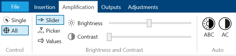
Measure Time, Peak and Tolerance are specified in a configuration file read at the app start and cannot be changed from the DISS6 user interface.
As a first step. please select channels for which to control brightness and contrast. At the hardware level each channels has independent brightness and contrast, however the software can assist with control of multiple channels by grouping them into a logical groups, such as all quadrants of a signal, or by selecting all channels in the detector.
- Single selection will only control brightness and contrast for the channel corresponding to the selected segment in the detector diagram. Click on the detector diagram to select desired segment.
- Grouped selection will control brightness and contrast of multiple channels, corresponding to the selected group of segment in the detector diagram. Click on the detector diagram to select desired group.
- All selection will control brightness and contrast for all channels in the detector.
Detector control does not have access to image brightness & contrast for display, as these belong to the scan controller, not the detector, therefore see the image B&C how to page!
DISS6 app
DISS6 app integrates control of and acquisition from majority hardware produced by point electronic GmbH, and therefore provides it provides brightness & contrast control of both detector and image. DISS6 software can group detector channels for global brightness & contrast control, or can use each channel with independent brightness & contrast controls. This 'global control' configuration for detectors is specified in a configuration file read at app start time and it cannot be changed during run time.
Measure Time, Peak and Tolerance are specified in a configuration file read at the app start and cannot be changed from the DISS6 user interface.
Independent control
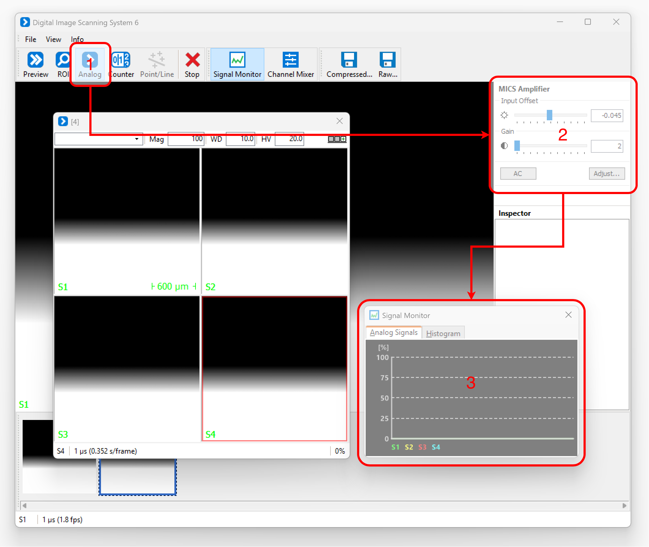
To adjust detector brightness & contrast on a particular channel,
- Click once on the appropriate scan profile button in the toolbar to start a new live scan with the desired channel. A new scan window will be shown, where the red border highlights the selected channel.
- Click on the desired channel in the scan window to select it and connect its brightness & contrast settings to the sliders in the MICS amplifier side panel.
- Adjust brightness (input offset) and contrast (gain) sliders in the MICS amplifier side panel, and note changes in the live scan.
- Adjust brightness & contrast such that live display in the Signal Monitor spreads the signal without clipping, preferably from 25% to 75% to account for drifts in signal due to sample shifts, charging or contamination. Alternatively, switch to the Histogram tab to use a live display for the selected channel.
Global control
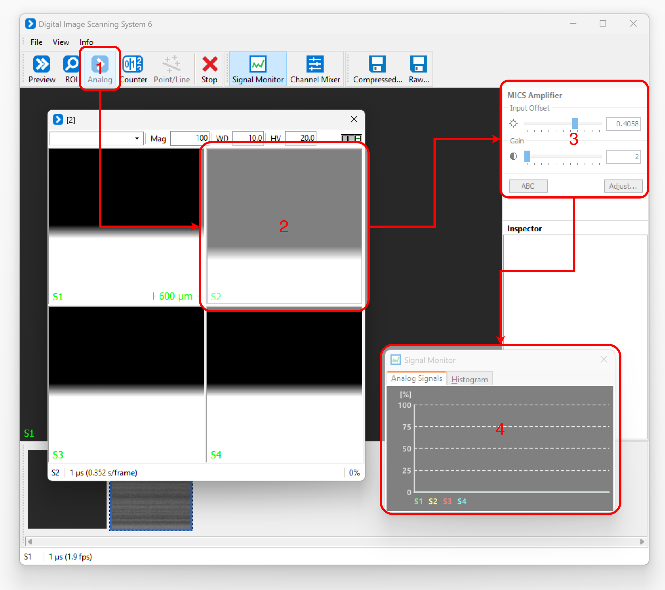
To adjust detector global brightness & contrast for all channels,
- Click once on the appropriate scan profile button in the toolbar to start a new live scan with the desired channel. A new scan window will be shown, where the red border highlights the selected channel. Brightness & contrast sliders in the MICS amplifier side panel will now become enabled and connected to the detector global controls.
- Adjust brightness (input offset) and contrast (gain) sliders in the MICS amplifier side panel, and note changes in the live scan.
- Adjust brightness & contrast such that live display in the Signal Monitor spreads the signal without clipping, preferably from 25% to 75% in the signal monitor - to account for drifts in signal due to sample shifts, charging or contamination.