Image brightness & contrast
Scan Control app
Controls for adjusting apparent image brightness and contrast on screen are given with the Range selection menu in the Palette section of the View toolbar.

Scan Control does not have access to detector brightness & contrast, as these belong to the detector, not the scan controller! Please see the Detector Control or DISS6 pages.
Palette gives control over how the image is displayed on screen, without any changes to image data. This is necessary because human vision is limited in the number of grayscale levels it can perceive. Whereas image data may contain 256 (8-bit) or 65,536 (16-bit) gray levels, human vision is limited to a much smaller number of gray levels that depend also on environment light and display specifications.
One approach is to map gray levels into different colors, where human vision excels, however this page will focus on adjustments for gray scale palette only.
Consider a 16-bit image where the minimum pixel value is 65 and maximum pixel value is 6,512. If the image is displayed at its full range where 0 is set to black and 65,535 is set to white, then the image will appear flat even if data is present.
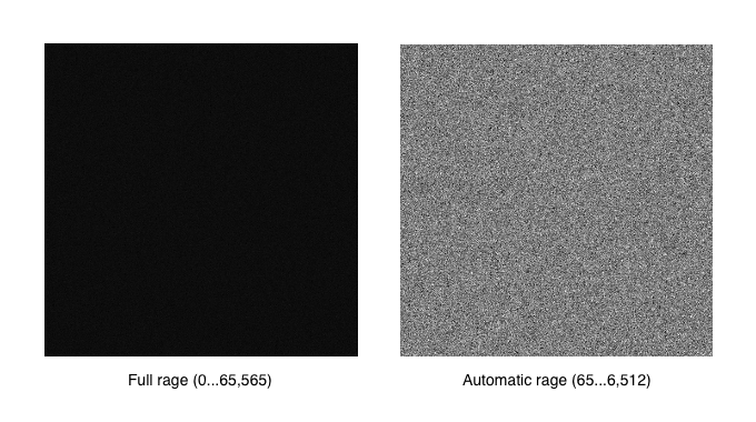
However if the same image is displayed with automatic range, where minimum pixel value of 65 is set to black and 6,512 is set to white, then the image content becomes visible.
For the first frame in the acquisition, Scan control will monitor each new image data chunk as it arrives from the scan controller and determine minimum and maximum pixel values in the current frame. Depending on signal levels in the frame, this may result in a continuous adjustment of black and white levels as the image is scanned. For the following frames, Scan control will use the minimum and maximum pixel values from the previous frame to avoid this dynamic scaling of black and white levels.
DISS6 app
DISS6 software can adjust the display of the image, without any change in image data, by manipulating the image palette so that black level corresponds to minimum pixel values and white level corresponds to maximum pixel values. This is also termed brightness & contrast, however it is achieved without any changes in the detector settings.
Correct detector brightness & contrast settings are required to ensure that raw signal is not clipped!
Display brightness & contrast control may be used individually for each single signal, or may be user globally for all signals in the scan. To change settings, please click right on the scan profile button and see section "Brightness/Contrast Automatic".
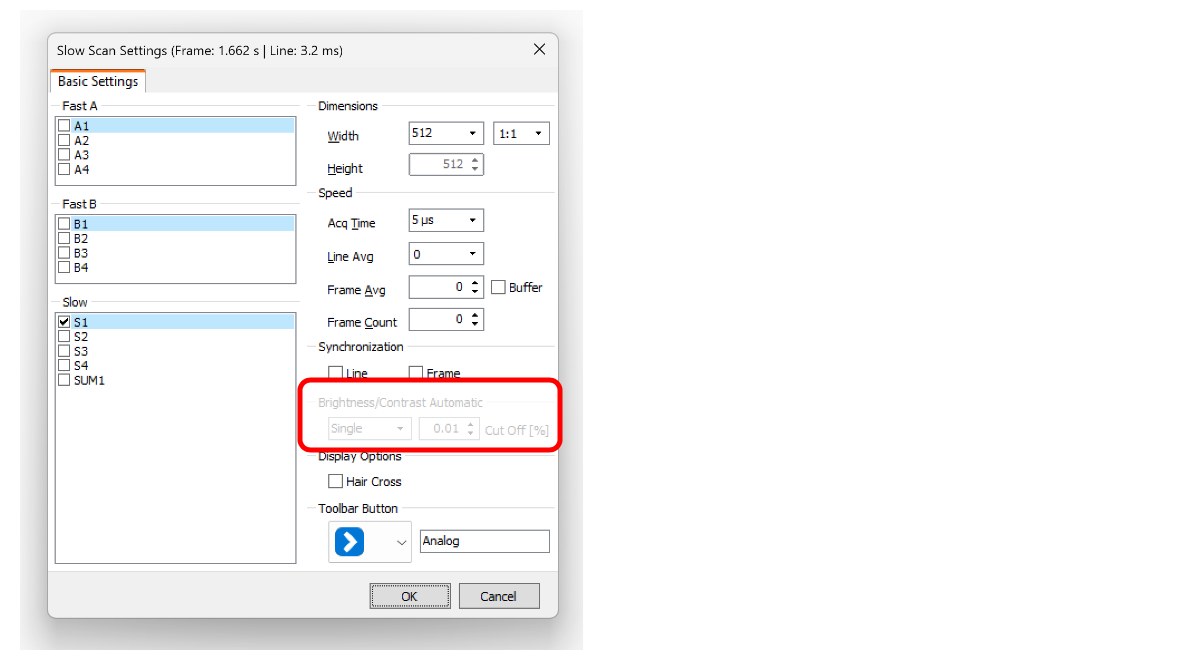
Black and white points are saved in image metadata, for each frame in the image, and are reused in the microDIP software. Further and more advanced changes in display brightness & contrast are available in the microDIP software.
Independent image B&C control
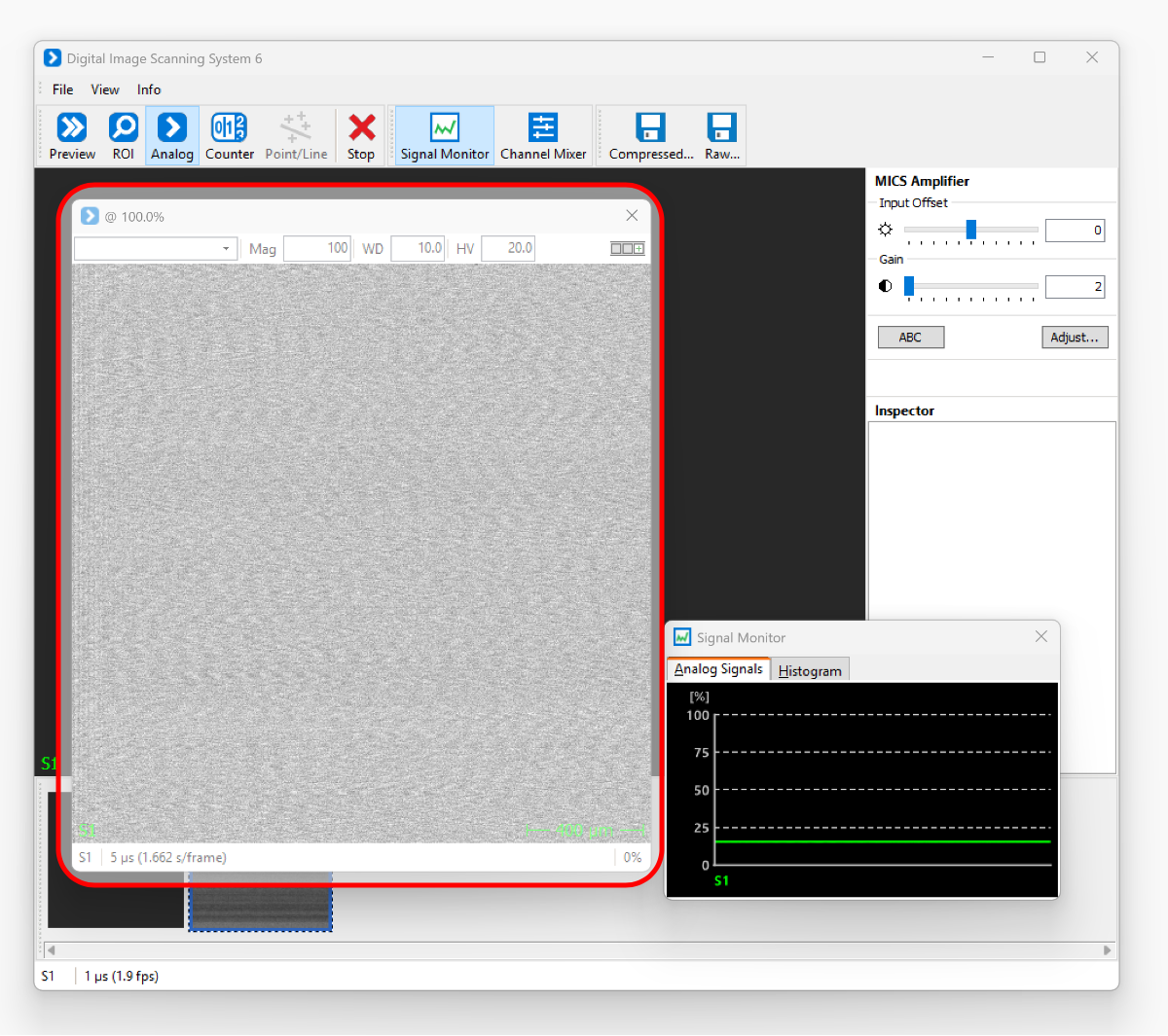
Each signal will be monitored independently to identify the minimum and maximum pixel values, with the specified cutoff (%), then the black and white levels will be defined accordingly. Each image will then have a different blank and white level. Note in the screenshot below how the display brightness & contrast are adjusted automatically to achieve strong contrast even for a very faint background noise - true scale is shown in the signal monitor as an apparent perfect green line.
Global image B&C control
All simultaneous signals will be monitored independently to identify the minimum and maximum pixel values, with the specified cutoff (%), then the same black and white levels will be defined for all images.